It's actually quite easy if you stick to a mental plan of using the bottom horizontal copper layers as the strips, and the top layer as vertical jumpers. This is a non circuit, but shows my attempt to use KiCad for strip board design. I also like to keep my components on one side and route wires on the other even when using double-sided board. if you're not using stripboard), and provide lots of room for edits to fix the mistakes I know I will make. I try to organize power busses with higher voltages at the top and ground at the bottom, route signals from left to right, color-code connecting wires (esp. Since these kinds of boards are usually for development purposes, make it spacious and easy to understand. Record where the strips should be left intact on one layer, and make wire jumpers on (an) other layer(s).Īfter that, it's up to you to create an intelligent layout. Use the "Draw Lines" tool on a non-copper layer (like Documents) to avoid confusing Eagle with respect to electrical connections. You might even want to diagram the strips. Now you can lay it out on a model of your stripboard. If you want to use Eagle PCB, configure the layout editor for 0.1" grid spacing, and display the lines: This seems to work well enough for most of the simple circuits that I make on perfboard. 2" graph paper for checking that an imagined layout will work. Usually, I just poke the components through. I will admit, however, that some projects fall into the middle of these categories. If it's just for a temporary project, solderless breadboards are also a great tool. BatchPCB and other prototype services can get you real, quality PCBs for (sometimes much) less than $50. We will post more tutorials soon, stay tuned with us.First, you don't need to do home PCB etching to get real circuit boards made. Hope this tutorial will give you a quick start on DipTrace. Now you can export or print your PCBs using the options given the File Menu.
PRINT OUT COLOR CODE DIPTRACE PARTS UPDATE
Right Click on Copper pour border > Update (Generally 6mm outer diameter and 4mm inner diameter).

Place mounting hole in each corner of the PCB design and you can edit it dimensions by right clicking on it. Next step is to add Mounting Hole, for that select Objects > Place Mounting Hole.In the connectivity option, select the net (Usually Ground net) in the Connect to Net and Thermals as 4 spoke. (Net name of a particular Pad or Trace can be find by right clicking on it). Then draw border of the PCB around the components and press enter after completing.Firstly Select Bottom Layer as given above. Copper Pour reduces noises, makes etching easy and provide strength to PCB. Next step is to add Copper Pour to PCB.Use this Drop Menu to Switch Layers – DipTrace After Routing is complete, top view and bottom view.To autoroute the PCB click Route > Run Autorouter.To set conductive trace width and trace clearance, go to Route > Route Setup.ĭiptrace Route Setup – Trace Width and Clearence.Mark Bottom Layer as Signal and Top as Plane. Go to Route option in menu bar and select Layer Setup. Here we need only Single Sided PCB (Copper conductive track on one side and Components on the other side).You can adjust the Solder Pad sizes such that you can properly solder it.Arrange the components so that they occupy minimum space.

PRINT OUT COLOR CODE DIPTRACE PARTS TRIAL
In this section we will start learning DipTrace by designing a small trial PCB.

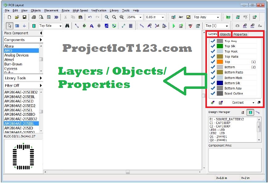
After completing the circuit diagrams, these are converted into PCB by using PCB Layout. The PCB Layout enables us to manually / automatically place components and route conductive tracks.

Circuit Diagrams can be drawn in Schematic Capture. Component Editor is for defining Symbol while Pattern Editor is for creating its Footprint. In these Component Editor and Pattern Editor allows us to create new components.


 0 kommentar(er)
